Integrator Notes
Field card 011, Dimmer + C4-KA auxiliary keypad: Line → dimmer BLACK, Load → dimmer RED, Neutrals → dimmer WHITE (+ keypad BLUE/WHITE), Ground → dimmer GREEN/YELLOW, Dimmer YELLOW → keypad YELLOW, Cap the unused wires, fold in
A4 · PDF · prints in black and white Open full size
Control4WiringCard 011

Control4 Dimmer + C4-KA auxiliary keypad

3-way wiring in 6 wires

Bench check pending

Written from official documentation and dealer sources, not yet run on our bench. Confirm on your hardware before you rely on it on a job.

The sequence

  1. Line → dimmer BLACK
  2. Load → dimmer RED
  3. Neutrals → dimmer WHITE (+ keypad BLUE/WHITE)
  4. Ground → dimmer GREEN/YELLOW
  5. Dimmer YELLOW → keypad YELLOW
  6. Cap the unused wires, fold in

More Control4

  • Field card 001: In-wall dimmer · switch · keypad
    No. 001Control4Factory reset

    In-wall dimmer · switch · keypad

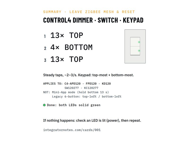
    Leave the Zigbee mesh and reset (13-4-13)

    1. Tap the TOP button 13×
    2. Tap the BOTTOM button 4×
    3. Tap the TOP button 13×
    Bench check pending
  • Field card 002: In-wall dimmer · switch · keypad
    No. 002Control4Identify

    In-wall dimmer · switch · keypad

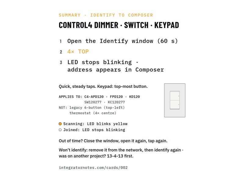
    Identify to Composer (4× TOP)

    1. Tap the TOP button 4×
    Bench check pending
  • Field card 003: SR-260 system remote
    No. 003Control4Factory reset

    SR-260 system remote

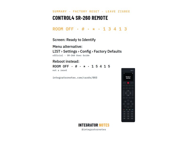
    Factory reset and leave Zigbee

    1. Press ROOM OFF
    2. Then # and *
    3. Then 1 · 3 · 4 · 1 · 3
    Bench check pending
Download PDF